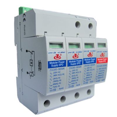
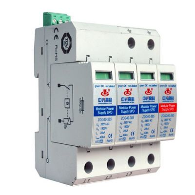
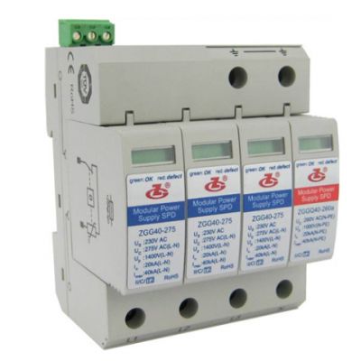
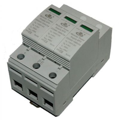
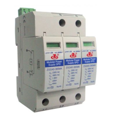
ZGG60-385 (3+1) Modular Power Supply SPD
Product code : 1489389960
The ZGG60-385 (3+1) Modular Power Supply SPD is made up of three varistor power supply modules and an air discharge tube power supply module for secondary protection of L-N and N-PE respectively. It is applied in the low voltage AC power distribution system, and connected between AC power supply and system equipment in parallel. It can prevent equipment from the impulse surge and transient overvoltage caused by the outside environment (such as lightning, EMI, etc.) or by the system (such as switching effects of the system, startup or shutoff of the inductance and capacitance load, etc.)
Features 1 Anti-reverse slot design;
2 High discharge capacity and low residual voltage;
3 Overtemperature protection;
4 Failure indication and centralized remote signalling alarm dry contacts;
5 IP20, UL94 V0 Technical Data
Operating Environment
.jpg)
- Technical Parameters
-
.jpg)
- Circuit Diagram
-
.jpg)
- Configuration
Overall dimensions: 90mm×72mm×67mm (excluding remote signalling terminals)
Standards Complied.jpg)
IEC 61643-1:2005 Surge protective devices connected to low-voltage distribution systems - Part 1: Technical requirements and testing methods
EN 61643-11/A11:2007 Low-voltage surge protective devices - Part 11: Surge protective devices connected to low-voltage power distribution systems
UL 1449 ed3 UL 1449 Third Edition
EN 60950-1:2006 Information technology equipment - Safety - Part 1: General requirements
YD/T 1235.2-2002 Testing methods for surge protective devices connected to low-voltage distribution systems of telecommunication stations / sites
Installation, Usage And MaintenanceInstallation
1 This product can only be installed and maintained by qualified professionals. The installation position cannot be touched by hands. Ensure that it is uncharged and check whether the SPD is all right before installation. If there’s damage or the display window is red, the SPD can not be used any more; if the window is green, the SPD is normal.
2 The SPD should be installed behind the fuse (FU1) of the power supply circuit, with the capacity of the fuse not exceeding 125A gL/gG; otherwise an 80A gL/gG fuse (FU2) should be provided in the surge protection branch circuit.
3 Refer to Fig. 3 for connection according to the marks on the SPD (L1 to SPD “L1”, L2 to SPD “L2”, and L3 to SPD “L3”; N to SPD “N”, and “” to PE). The sectional area of the connecting line must be more than 4 mm2 and be as short as possible.
4 Connection of remote signalling alarm: the SPD is provided with remote signalling interfaces (1 and 2 normally closed, and 2 and 3 normally open), applicable for remote centralized monitoring or alarm.
5 After the connection, check if the module is fitted in. If so, 1 and 2 are closed, and 2 and 3 are open; if not, repress the module.Wiring diagram
.jpg)
Usage and Maintenance
1 After failure, the SPD shall be automatically disconnected with the power supply circuit through the internal thermal fuse system, the display window changes to “Red” from “Green”, and remote signalling interfaces 1 and 2 are open and 2 and 3 are closed. When the degradation display window is “Red” or there’s a remote alarm signal, the SPD should be changed immediately.
2 The display window of the SPD must be checked after the lightning storm.
.png)

