.png "Trang chủ")

")
Bộ cấp nguồn SPD mô-đun ZGG40-385 (3 + 0)
Mã sản phẩm : 1490068977
Bộ cấp nguồn mô-đun ZGG40-385 (3 + 0) là loại bảo vệ chống sét cấp nguồn cấp độ C bao gồm ba mô-đun bảo vệ nguồn cung cấp loại MOV có thể cắm để bảo vệ L-PE. Nó được áp dụng trong hệ thống phân phối điện xoay chiều điện áp thấp và được kết nối song song giữa nguồn điện AC và thiết bị. Nó có thể ngăn chặn thiết bị khỏi sự tăng xung và quá điện áp nhất thời do môi trường bên ngoài (như sét, EMI, v.v.) hoặc bởi hệ thống (chẳng hạn như hiệu ứng chuyển mạch của hệ thống, khởi động hoặc tắt điện cảm và tải điện dung...)
Đặc trưng
1 Thiết kế khe chống ngược;
2 Khả năng phóng điện cao và điện áp dư thấp;
3 Bảo vệ quá nhiệt;
4 Chỉ báo lỗi và báo động tiếp xúc báo động từ xa tập trung;
5 IP20, UL94 V0 1 Dữ liệu kỹ thuật
Môi trường hoạt động
|
Nhiệt độ |
-40 °C ~ 80 °C |
|
Độ ẩm tương đối |
≤95% (25°C) |
|
Độ cao (so với mực nước biển) |
≤ 3000m |
Các thông số kỹ thuật
|
Mô-đun |
ZGG40-385(3+0) |
|
SPD theo chuẩn IEC61643-1 |
Hạng II |
|
SPD theo chuẩn EN 61643-11 |
Loại 2 |
|
Điện áp hoạt động định danh Uo |
230V AC |
|
Điện áp hoạt động liên tục tối đa Uc |
385V AC |
|
Tần số hoạt động |
50/60HZ |
|
Dòng xả định danh In (8/20µs) |
20kA |
|
Dòng xả tối đa Imax (8/20µs) |
40kA |
|
Mức độ bảo vệ điện áp Uo |
1.8 kV |
|
Bảo vệ quá dòng nguồn điện chính |
125A gL/gG |
|
Dòng rò |
≤20µA |
|
Chế độ kết nối |
Song song |
|
Chế độ bảo vệ |
L-PE |
|
Thời gian phản hồi T |
≤25ns |
|
Tiết diện của thiết bị đầu cuối kết nối |
Đa lõi: 4-25mm2, lõi đơn: 4-35mm2 |
|
Diện tích kết nối tối đa của thiết bị đầu cuối tín hiệu từ xa |
1.5mm2 |
|
Cường độ tiếp xúc báo động tín hiệu từ xa |
AC: 250V/0.75A 125V/3A DC: 30V/2A |
|
Sự phân tách giữa mạch báo động và mạch chủ |
Sự cách điện tăng cường được áp dụng giữa mạch báo động và mạch chủ (với Uo không vượt quá 230V theo chuẩn EN 60950-1:2006. Nó có thể chịu được điện áp cách điện 3000Vrms) |
|
Mô men xoắn: Kết nối giao diện tín hiệu từ xa/ thiết bị đầu cuối |
4.5/ 0.25Nm |
|
Chất liệu vỏ bọc |
PBT V-0 |
|
Mức độ bảo vệ của vỏ bọc (mã IP) |
IP20 |
|
Hình thức lắp đặt |
Đường ray dẫn hướng tiêu chuẩn DIN 35mm |
|
Hệ thống áp dụng |
TT, IT |
|
Cân nặng |
420±5g |
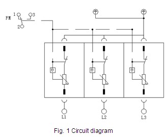
Sơ đồ mạch
Cấu hình
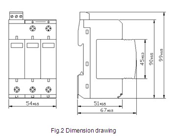
Kích thước: 90mm × 54mm × 67mm (không bao gồm các thiết bị đầu cuối báo hiệu từ xa)
Tiêu chuẩn tuân thủ
IEC 61643-1: 2005 Thiết bị bảo vệ tăng áp được kết nối với hệ thống phân phối điện áp thấp - Phần 1: Yêu cầu kỹ thuật và phương pháp thử nghiệm
EN 61643-11 / A11: 2007 Thiết bị bảo vệ đột biến điện áp thấp - Phần 11: Thiết bị bảo vệ tăng áp được kết nối với hệ thống phân phối điện áp thấp
UL 1449 ed3 UL 1449 Phiên bản thứ ba
EN 60950-1: 2006 Thiết bị công nghệ thông tin - An toàn - Phần 1: Yêu cầu chung
YD / T 1235.2-2002 Phương pháp thử nghiệm cho các thiết bị bảo vệ đột biến được kết nối với hệ thống phân phối điện áp thấp của các trạm / địa điểm viễn thông
Cài đặt, sử dụng và bảo trì
Cài đặt
1 Sản phẩm này chỉ có thể được cài đặt và bảo trì bởi các chuyên gia có trình độ. Vị trí lắp đặt không thể chạm vào bằng tay. Đảm bảo rằng nó không được cấp nguồn và kiểm tra xem SPD có ổn không trước khi cài đặt. Nếu có thiệt hại khác hoặc cửa sổ hiển thị màu đỏ, SPD không thể được sử dụng nữa; nếu cửa sổ màu xanh lá cây, SPD là bình thường.
2 SPD nên được lắp đặt phía sau cầu chì (FU1) của mạch cấp nguồn, với công suất của cầu chì không vượt quá 125A gL / gG; mặt khác, cầu chì 80A gL / gG (FU2) phải được cung cấp trong mạch nhánh bảo vệ đột biến.
3 Tham khảo hình 3 để biết kết nối theo các dấu trên SPD. Diện tích mặt cắt của đường kết nối phải lớn hơn 4mm2 và càng ngắn càng tốt.
4 Kết nối báo động báo hiệu từ xa: SPD được cung cấp các giao diện báo động báo hiệu từ xa (1 và 2 thường đóng và 2 và 3 thường mở), áp dụng cho giám sát hoặc báo động tập trung từ xa.
5 Sau khi kết nối, kiểm tra xem mô-đun có được lắp vào không. Nếu vậy, 1 và 2 được đóng lại, và 2 và 3 đang mở; nếu không, ấn lại mô-đun.
Sơ đồ hệ thống dây điện
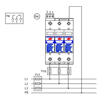
Fig. 3 Wiring diagram
Sử dụng và bảo trì
1 Sau khi thất bại, SPD sẽ tự động ngắt kết nối với mạch cấp nguồn thông qua hệ thống cầu chì nhiệt bên trong, cửa sổ hiển thị thay đổi thành từ “Đỏ” sang “Xanh”, và các giao diện báo hiệu từ xa 1 và 2 được mở và đóng 2 và 3. Khi cửa sổ hiển thị xuống cấp là màu đỏ hay có một tín hiệu báo động từ xa, SPD sẽ được thay đổi ngay lập tức.
2 Cửa sổ hiển thị của SPD phải được kiểm tra sau cơn bão.
Sản phẩm cùng loại

")
")
 z")
SẢN PHẨM VẬT TƯ THIẾT BỊ VIỄN THÔNG
- DELTA ELECTRONICS
- ZHONG GUANG
- KINGSIGNAL
- OCRE
- MICRODATA
- VẬT TƯ VIỄN THÔNG


.png "Kingsignal")


